
Limit Switch Guide for Industrial Machine Control
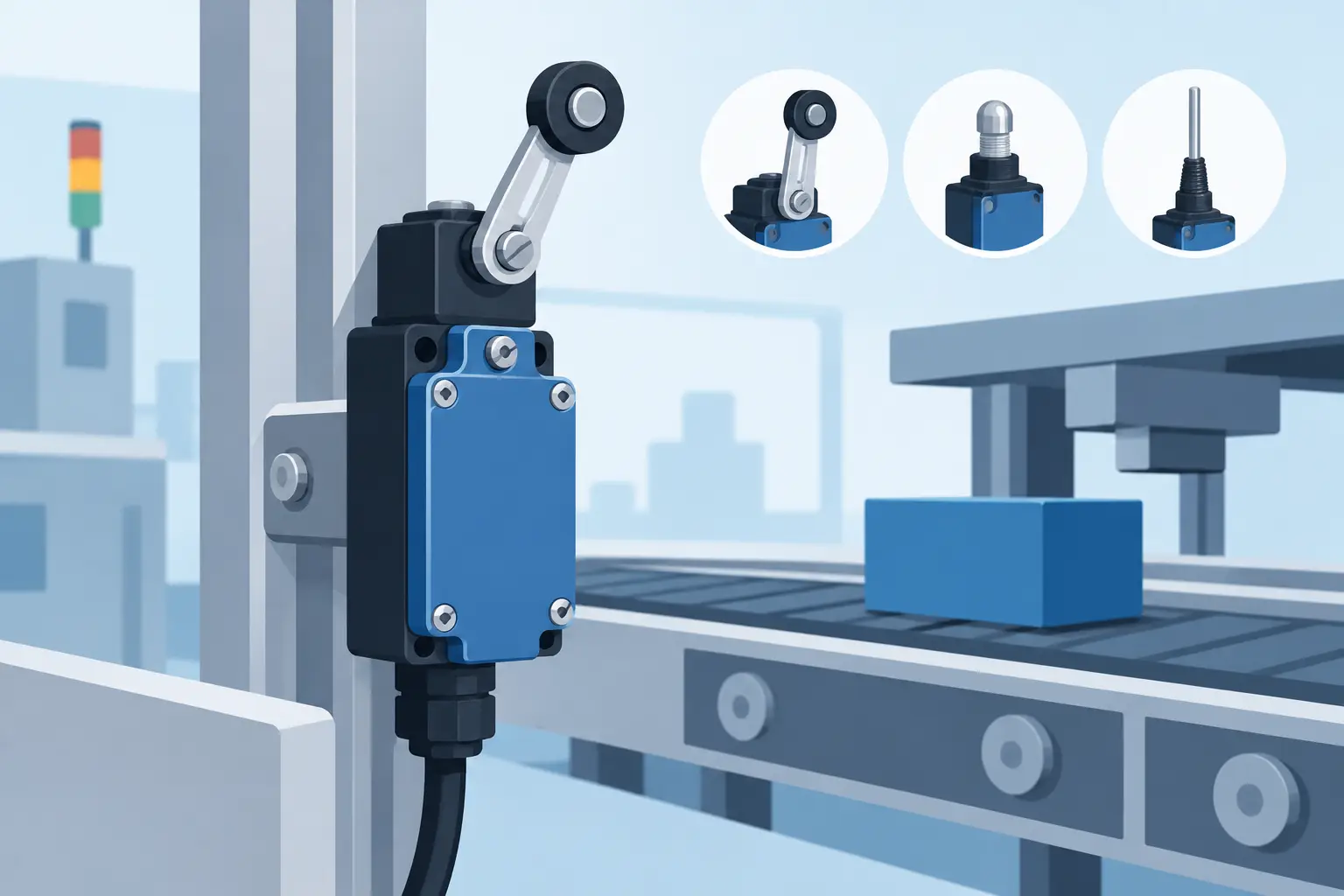
A limit switch is often a small component with a large operational consequence. When it confirms that a guard is closed, a cylinder has reached end of travel, or a conveyor diverter is in position, the control system can continue its sequence. When it fails or is incorrectly selected, the result may be nuisance faults, damaged equipment, or unplanned downtime. This limit switch guide covers the specifications that matter when selecting, replacing, and installing industrial limit switches.
What a Limit Switch Does in a Control System
A limit switch is an electromechanical position sensor. Physical contact with an object, cam, lever, or machine feature moves an actuator and changes the state of one or more electrical contacts. The PLC, relay logic, drive circuit, or safety circuit then uses that signal to make a decision.
Common applications include end-of-stroke verification on pneumatic and hydraulic equipment, pallet detection, door and guard position monitoring, travel limits on hoists, packaging machinery, and part presence confirmation. Unlike non-contact proximity sensors, a mechanical limit switch requires the target to physically actuate it. That contact-based operation is useful where the target material varies or where a defined mechanical switching point is needed.
The right device depends on more than whether it is normally open or normally closed. Actuator movement, contact configuration, electrical load, enclosure rating, mounting pattern, and cable entry all affect whether the switch will perform reliably in the application.
Limit Switch Guide: Start With the Motion
Before comparing manufacturers or part numbers, define what physically moves the switch actuator. This determines the actuator style and helps prevent premature failure.
A plunger actuator works well when the moving object approaches the switch in a straight, controlled path. Roller plungers reduce friction when a cam or moving surface contacts the switch. Lever arms and roller levers suit applications with a wider approach angle or longer actuation distance, such as conveyor mechanisms and rotating cams. Adjustable rod or spring rod actuators can accommodate irregular movement, but they are more vulnerable to bending, vibration, and accidental impact.
The actuator must have enough travel to reach the operating point without being forced beyond its allowable overtravel. This is a frequent field issue. A switch may work during commissioning but fail after repeated impacts because the machine component is striking the actuator too aggressively. Review the datasheet for pretravel, operating position, overtravel, and total travel rather than setting a cam by visual estimate alone.
Actuation direction matters as well. A side rotary lever may be appropriate for a cam passing left to right, while a top plunger is better for vertical travel. If the target can approach from multiple directions or is misaligned, reconsider the mounting arrangement instead of relying on an actuator that is not designed for side loading.
Select Contacts for the Actual Circuit
Contact configuration is the next decision. A common industrial arrangement is one normally open and one normally closed contact, often described as 1NO/1NC or SPDT changeover. The NO contact closes when the switch actuates. The NC contact opens when it actuates.
For standard machine feedback, either contact type may work if the PLC input logic is configured correctly. For fault detection, an NC circuit is often preferred because a broken wire or loose terminal can appear as a fault rather than a normal condition. That does not automatically make every NC switch suitable for a safety function.
Safety-related guarding and emergency stopping require an engineered safety circuit. Where the application calls for it, use devices with positive opening contacts and the required safety approvals, then validate the complete circuit to the applicable machine safety requirements. A general-purpose limit switch should not be substituted for a safety interlock simply because it has an NC contact.
Check the electrical rating at the voltage and load type in the real circuit. Switching a PLC input is a low-current task. Switching a solenoid valve, contactor coil, brake, or motor load presents inductive current and can shorten contact life. DC loads can be particularly demanding because the arc does not naturally pass through zero as it does on AC. If the switch controls an inductive load directly, confirm its DC and AC ratings and use appropriate suppression where required.
Also compare the minimum switching current for low-level signals. Contacts designed for higher-power loads may not perform consistently in very low-current circuits if contamination or oxidation is present. In those cases, a sensor or a switch with suitable low-level contact specifications may be the better fit.
Match the Housing to the Environment
A limit switch that is correct electrically can still fail early if its enclosure does not match the operating area. Washdown equipment, outdoor conveyors, foundry environments, food processing lines, and dusty packaging operations place very different demands on seals, housings, and cable connections.
Review the required IP or NEMA rating, but do not stop there. Consider chemical exposure, temperature range, vibration, humidity, oil mist, and direct washdown pressure. A metal housing can offer strong mechanical protection in high-impact areas. A compact plastic body may be appropriate inside a protected machine enclosure where space and wiring access are limited.
Cable entry is part of the environmental decision. A prewired cable reduces possible entry points and speeds installation, but replacing a damaged cable may require replacing the complete switch. Connectorized models simplify changeout and reduce downtime when a compatible cordset is stocked. Conduit-entry models provide flexibility for field wiring but depend on correct gland selection and installation to maintain the enclosure rating.
For applications with frequent washdown or vibration, pay close attention to connector orientation, cable strain relief, and the stated rating of the mated connection. The switch body may be rated for harsh conditions while the installed cable assembly becomes the weak point.
Verify Mechanical and Electrical Compatibility Before Ordering
For an existing machine, the safest replacement process begins with the complete catalog number on the installed part. Manufacturer, series, actuator code, contact block, connector type, and special approvals can all be embedded in a single model number. A visually similar switch can have a different contact sequence, operating force, or mounting dimension.
When the original part number is unavailable, document the mounting centers, actuator type, head orientation, contact arrangement, voltage and current duty, cable entry, enclosure requirement, and any approvals shown on the label. Photos of the label, actuator, mounting face, and wiring terminations help reduce identification errors.
Cross-brand replacement can be practical, but it should be treated as an engineering decision, not a cosmetic match. Confirm dimensions, switching positions, terminal layout, and ratings against the machine documentation. A replacement may fit the mounting holes yet switch too early or too late in the stroke.
Industrial buyers supporting mixed equipment fleets may need devices from Siemens, Schneider Electric, Omron, Allen-Bradley, Sick, IFM, or other established manufacturers. Purchasing by full part number remains the best route when exact compatibility is required. For planned maintenance, keeping a verified replacement record alongside the machine bill of materials avoids repeating the identification process during a breakdown.
Installation Details That Prevent Nuisance Failures
Mount the switch on a rigid surface and use the manufacturer-recommended hardware and torque. A bracket that flexes under normal machine movement can create inconsistent switching points. After mounting, position the target so it actuates the device within its rated travel range, with enough margin for normal wear and minor machine variation.
Do not use the switch body as a mechanical stop. The moving mechanism should stop independently, with the limit switch serving as a signal device or secondary limit as designed. Repeated hard impact can damage the actuator, alter the switching point, or crack the housing.
During wiring, verify the terminal numbering rather than assuming contact positions. Check the circuit with a meter before placing the machine back in service, then test operation at slow speed where possible. Confirm both the expected actuation point and release point. On a PLC-controlled machine, check the input status and confirm that the program responds as intended.
Diagnosing a Failed or Intermittent Limit Switch
When a machine reports a position fault, do not assume the switch is the only cause. Inspect the actuator for damage, verify that the target still reaches it, and look for loose brackets, bent cams, contamination, or cable damage. A limit switch can test correctly by hand while failing in operation because the machine no longer provides enough travel to actuate it.
Use a meter to check contact state with power removed when safe procedures allow. Then evaluate the input circuit, terminal tightness, connector condition, and PLC input indicator. If the switch controls a load directly, inspect for contact wear caused by inrush or inductive arcing. Replacing the device without correcting the load condition may only provide a temporary fix.
A correctly specified limit switch supports repeatable machine motion and faster fault isolation. When ordering a replacement, match the complete part number whenever possible, verify the mechanical actuation details, and keep a documented spare for equipment where a single failed switch can stop production.