
How to Inspect Pneumatic Cylinders Safely
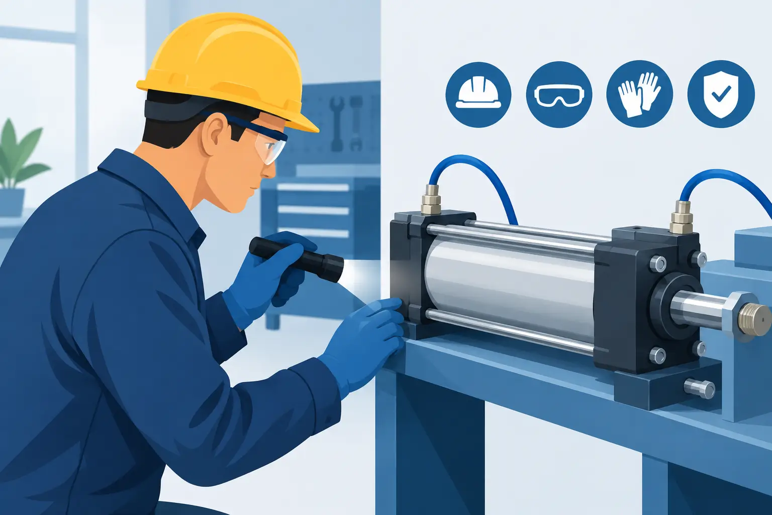
A pneumatic cylinder rarely fails without warning. A slower extension stroke, a faint air leak at the rod seal, or a loose clevis pin can signal a developing problem long before the actuator stops a machine. Knowing how to inspect pneumatic cylinders gives maintenance teams a practical way to protect uptime, identify replacement requirements early, and avoid damage to connected tooling.
A useful inspection is more than a quick look for oil or loose hardware. It should confirm that the cylinder is mechanically secure, receiving suitable air supply, moving through its full stroke, and holding its position as the machine requires. The right checks depend on the cylinder style, duty cycle, load, and environment, but the process below applies to most ISO, NFPA, compact, tie-rod, and guided pneumatic cylinders used in industrial equipment.
Start With a Safe Inspection Condition
Before touching the actuator, place the machine in a safe condition using the site's lockout/tagout procedure. Isolate the pneumatic supply, bleed trapped air from the circuit, and verify that the cylinder and attached load cannot move unexpectedly. Vertical loads, spring-loaded mechanisms, and tooling with stored mechanical energy need separate support before air pressure is removed.
Do not assume a directional valve has fully exhausted the cylinder. A blocked exhaust, closed flow control, or leaking valve spool can leave pressure on one side of the piston. Check the pressure gauge where available and carefully verify that motion has stopped before servicing mounts, fittings, sensors, or the rod end.
For troubleshooting under operating conditions, keep personnel clear of moving equipment and follow approved machine-safety procedures. Some faults only appear at normal pressure or speed, but a live test should be deliberate, controlled, and performed by qualified personnel.
How to Inspect Pneumatic Cylinders: External Checks
Begin with the cylinder body, rod, end caps, mounts, and air connections. Dirt can hide the source of a leak or make a damaged component look serviceable, so clean the exterior first when practical. Avoid abrasive cleaning methods that can scratch a polished rod or damage sensor grooves.
Look closely at the piston rod. It should be straight, smooth, and free of scoring, pitting, corrosion, dents, and peeling plating. Even minor rod damage can cut the rod seal during each stroke, leading to air loss and early seal failure. A film of lubricant may be normal on some applications, but a persistent accumulation of oil and dirt around the rod gland usually points to a worn seal, excessive lubrication, or contaminated air.
Inspect the barrel for dents, corrosion, cracks, or signs that the tube has shifted relative to its end caps. On tie-rod cylinders, check for bent, corroded, or loose tie rods and damaged nuts. Do not tighten tie-rod nuts to an assumed value. Cylinder manufacturers specify assembly torque, and uneven or excessive tightening can distort the tube, compromise seals, or create rod binding.
Examine the mounting arrangement as carefully as the cylinder itself. Loose foot mounts, cracked trunnions, worn pivot pins, elongated clevis holes, and loose rod-end hardware all transfer side load into the actuator. A cylinder is designed primarily for linear force. If it is also being used to guide a load, the rod and bearings can wear rapidly. Guided cylinders or external linear guides are often needed where the tooling can shift, twist, or overhang the rod.
Check ports, fittings, tubing, silencers, and flow controls for cracks, stripped threads, damaged tubing, or contamination. Tubing that rubs against moving machine members may eventually split and create an intermittent fault that is difficult to locate.
Check for Air Leaks and Seal Failure
With the system returned to a controlled operating condition, inspect for audible leaks at the rod seal, end-cap seals, ports, valve connections, and tubing. A handheld ultrasonic leak detector is effective in noisy production areas. For accessible, low-risk locations, an approved leak-detection solution can reveal bubbles at fittings and seals.
A leak at the rod gland during movement often indicates rod-seal wear or rod damage. Leakage from an end cap may point to an aging static seal, loose assembly hardware, barrel damage, or improper reassembly. Leakage from the exhaust port of the directional valve while the cylinder should be holding can also indicate internal bypass across the piston seal or a valve problem.
Separate cylinder leakage from valve leakage before ordering parts. Isolate the cylinder where the circuit design allows, then observe whether pressure decays on the pressurized side. If the cylinder drifts under load with the valve blocked or isolated, internal piston-seal bypass is more likely. If the condition changes when the valve is replaced or manually actuated, the directional valve may be the source.
Observe Stroke, Speed, and End-of-Travel Behavior
Cycle the actuator through its normal operation and observe both extension and retraction. The motion should be repeatable, without hesitation, chatter, bounce, or a sharp impact at either end of travel. Slow movement may result from low supply pressure, restricted tubing, clogged silencers, incorrectly adjusted flow controls, undersized valves, contamination, or internal friction.
A cylinder that moves smoothly when unloaded but stalls under process load may be undersized, operating at inadequate pressure, or encountering mechanical resistance. Confirm the actual load and available bore-area force rather than relying only on the original cylinder size. Force differs between extension and retraction because the rod reduces effective piston area on the retract side.
Pay attention to cushioning. Adjustable cushions should decelerate the piston near the end of stroke without causing a hard stop or excessive delay. If adjustment has little effect, the cushion seal, cushion needle, or internal components may be worn. Do not use flow controls as a substitute for proper end-of-stroke cushioning on high-speed or high-mass applications.
Verify Alignment and Side Load
Misalignment is a common reason otherwise sound cylinders wear out early. During a slow manual cycle, watch the rod and connected load from the side. The rod should enter and leave the cylinder in a straight line, without visible flexing or lateral movement. A rod that bends during extension is under side load, even if the cylinder still completes the stroke.
Check linkage geometry at several points in the stroke. Pivot mounts need to rotate freely, and the rod-end joint must accommodate the travel path without forcing the rod sideways. Misalignment may become more severe near one end of travel as fixtures shift or guides wear.
For cylinders driving slides, clamps, or packaging tooling, inspect the external guides and bearings. Replacing only the cylinder may provide a short-term fix if worn guides continue to load the new rod and piston bearings. Record the mounting style, bore, stroke, rod thread, port size, sensor type, and any guide or cushioning features before sourcing a replacement.
Inspect Sensors and Position Feedback
Many pneumatic cylinders use magnetic piston sensors to confirm extended, retracted, or intermediate positions. Verify that each sensor is secure in its groove or clamp, correctly positioned, and protected from impact. Check sensor cables for crushed insulation, loose connectors, and strain at cable entry points.
Use the machine input status or a meter to confirm that the sensor switches at the intended point in the stroke. A sensor may show an indicator light while the control input remains off because of wiring, connector, or PLC input issues. Conversely, a correctly functioning sensor can reveal a mechanical problem when the piston no longer reaches its expected end position.
Review Air Quality and Operating Conditions
Repeated cylinder failures often start upstream. Inspect filters, regulators, lubricators where used, drains, and air preparation units. Water, rust particles, compressor oil carryover, and incompatible lubricants can damage seals and stick valves. Excessive pressure can shorten service life, while low or unstable pressure reduces available force and creates inconsistent cycle times.
Compare the application against the cylinder's rated pressure, temperature, speed, and environmental limits. Standard seals may not suit washdown, high heat, abrasive dust, chemical exposure, or food-processing requirements. In those cases, seal material, rod coating, mounting design, and cylinder construction matter as much as bore and stroke.
Document Findings Before Ordering a Replacement
Record what was observed: leak location, pressure at the cylinder, cycle behavior, rod condition, mount wear, sensor status, and whether the fault occurs under load. Take clear photos of the nameplate and mounting details. The manufacturer, exact part number, bore, stroke, port configuration, and sensor compatibility are all relevant when selecting a direct replacement.
If the original part number is unavailable, match the functional requirements rather than choosing a cylinder by outside dimensions alone. Mounting centers, rod-end thread, stroke tolerance, magnetic piston design, cushioning, and seal material can affect fit and performance. For critical equipment, confirm compatibility with the machine documentation and connected hardware before placing an order.
A cylinder inspection is most valuable when it turns an early symptom into a scheduled repair. Catching a scored rod, leaking seal, or worn mount before the next production run gives the maintenance and procurement teams time to secure the correct component instead of making a rushed substitution during downtime.