
Choosing a Solenoid Valve for Pneumatic Systems
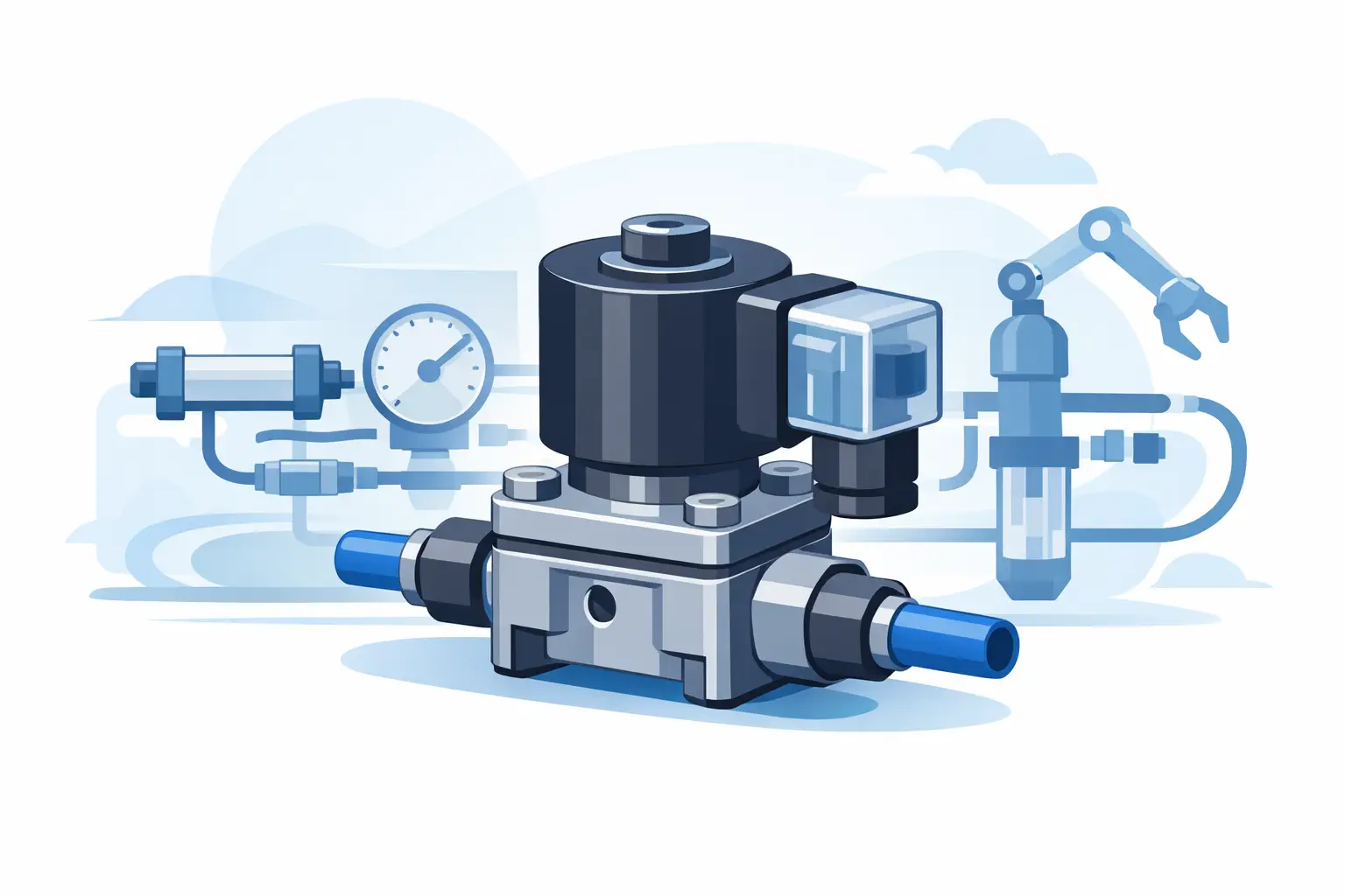
A cylinder that will not extend, a gripper that releases at the wrong time, or a machine that loses cycle speed can often be traced to one component: the solenoid valve for pneumatic systems. The valve may look like a straightforward on-off device, but its configuration determines how compressed air is routed, exhausted, held, or released. Selecting the wrong function, coil voltage, or flow capacity can create problems that appear elsewhere in the machine.
For maintenance teams and controls engineers, the practical goal is not simply to find a valve that fits the port. It is to identify a replacement or new component that matches the circuit design, actuator behavior, electrical controls, air supply, and operating environment.
Selecting a Solenoid Valve for Pneumatic Systems
A pneumatic solenoid valve uses an energized coil to shift an internal poppet, spool, or pilot mechanism. That movement changes the air path between supply ports, work ports, and exhaust ports. The basic purpose is simple, but the valve architecture must match the actuator and the required machine state when power is present or removed.
Start with valve function. A 2/2 valve has two ports and two positions, making it suitable for basic air isolation or flow control. A 3/2 valve commonly operates a single-acting cylinder, spring-return actuator, blow-off circuit, or pneumatic signal. A 5/2 valve is widely used for double-acting cylinders because it alternates pressure between two work ports while exhausting the opposite side. A 5/3 valve provides a center position, but the center condition matters: it may block ports, exhaust the actuator ports, or pressurize them.
Do not treat these designations as interchangeable. Replacing a 5/2 valve with a 5/3 version, even when the ports and coil connector appear similar, can change what happens during a stop command or power loss. In a packaging machine, that difference may affect whether a cylinder holds position, retracts, or becomes free to move.
Normal state and actuation method
For a 3/2 valve, normally closed means supply air is blocked in the de-energized state and the outlet is typically exhausted. Normally open means air is available without coil power. This is often a safety or process decision rather than a convenience decision. Determine what the equipment must do when a control output drops out.
Also verify whether the valve is single-solenoid, double-solenoid, spring return, or detented. A single-solenoid, spring-return valve returns to its default state when power is removed. A double-solenoid valve generally remains in its last shifted position until the opposite coil is energized, depending on the design. That memory behavior can be useful for a sequence, but it must be understood during startup, emergency stops, and troubleshooting.
Match Flow Capacity to the Actuator
Port thread size does not establish adequate airflow. A valve with a larger connection can still have a restrictive internal passage, while a compact valve may provide sufficient flow for a small-bore cylinder. Review the manufacturer’s Cv, Qn, or standardized flow rating and compare it with the actuator volume, tubing length, cycle rate, and required stroke time.
Undersized flow capacity usually appears as slow extension or retraction, inconsistent cycle time, and pressure drop at the cylinder. Oversizing is less likely to prevent operation, but it can increase cost, air consumption, and the difficulty of controlling a fast-moving load. The correct choice depends on the application. A high-speed pick-and-place axis has different requirements than a clamp that cycles a few times per hour.
Pressure specifications need the same attention. Confirm the normal supply pressure, maximum allowable pressure, and the valve’s operating range. Pilot-operated valves may require a minimum pressure differential to shift reliably. If the circuit runs at low pressure, uses vacuum, or must operate from zero pressure, a direct-acting or externally piloted design may be necessary.
Air quality also affects service life. Water, oil carryover, pipe scale, and fine particles can cause sticking, internal leakage, or slow response. Verify the recommended filtration level and confirm that the valve materials are compatible with lubricated or non-lubricated air. If the machine is exposed to washdown, outdoor conditions, heat, or chemical vapors, check enclosure ratings, seal material, and ambient temperature limits instead of assuming a standard valve will last.
Confirm the Electrical Details Before Ordering
A valve body can be mechanically correct and still fail to operate if the coil does not match the control circuit. Confirm whether the machine uses 24 VDC, 120 VAC, 230 VAC, or another coil voltage. DC coils are common in PLC-controlled equipment because they work directly with transistor outputs and provide predictable switching behavior. AC coils may be present in older machinery or relay-controlled panels.
Check coil power consumption against the available output capacity. This is particularly relevant when several solenoids are energized from one output group or a remote I/O module. A coil with excessive inrush or holding current can overload an output, while an incorrect AC or DC coil may overheat or fail to shift the valve.
Connector style should be verified as well. DIN-style connectors, flying leads, M8 and M12 connections, and fieldbus valve terminals all have different wiring and service requirements. For a replacement, record the connector orientation, cable clearance, indicator light requirement, and suppression method. A surge-suppressed coil may protect a DC output, but it can also slightly affect de-energization time in applications requiring fast release.
Consider Mounting, Manifolds, and Service Access
Standalone inline valves work well for simple circuits, but valve manifolds reduce tubing, simplify wiring, and make multi-axis machines easier to service. A manifold installation requires more than matching the valve series. Check the station count, end plates, blanking plates, common supply and exhaust configuration, and whether individual stations can be replaced without disturbing the rest of the bank.
For OEM support and MRO work, exact mounting geometry is often decisive. Compare port location, thread standard, mounting hole pattern, valve width, exhaust arrangement, and coil access. NPT and metric threads are not interchangeable. Nor are visually similar valves from different product families, even when both are described as 5/2 pneumatic solenoid valves.
If the valve controls a guided cylinder, rodless actuator, or gripper, review the actuator manufacturer’s circuit recommendation. Some applications require flow controls at the cylinder ports, quick-exhaust valves, soft-start behavior, or a particular center condition to manage load movement. The directional valve is only one part of the pneumatic circuit.
A Practical Replacement Verification Process
When a failed valve is on a running machine, part-number accuracy comes before substitution. Read the full manufacturer label, including the valve series, function, port size, coil voltage, and any suffix characters. Suffixes may identify manual overrides, seal compounds, wiring options, pilot configuration, or regional thread standards.
Before submitting a purchase request, collect these details:
- Manufacturer, complete part number, and a clear label photo
- Valve function, port count, and normal or center position
- Coil voltage, current type, connector type, and number of coils
- Port thread size, tubing or fitting requirements, and mounting style
- Operating pressure, media condition, and ambient environment
- Whether the valve is individual-mounted or installed on a manifold
This information helps prevent an urgent replacement from becoming a second downtime event. It also gives purchasing teams enough detail to compare approved options across established manufacturers such as Festo, Siemens, Schneider Electric, Omron, SMC, and other pneumatic-control suppliers used in the facility.
When an Exact Replacement Is Not Available
A cross-reference can be appropriate, but only after the application requirements are documented. A substitute must match the directional function, pressure range, flow requirement, electrical characteristics, mechanical interface, and safety behavior. A valve that shifts correctly on the bench may still be unsuitable if it changes fail-state behavior or requires an unavailable manifold base.
For legacy equipment, it may be more practical to replace a valve, base, and connector together than to force-fit a newer component into an obsolete interface. That decision depends on downtime tolerance, spare-parts strategy, and the number of identical machines in service. For repeat installations, standardizing the replacement family can simplify future stocking and technician training.
American Automation 24 supports part-number-driven sourcing across industrial automation brands, which is useful when maintenance and procurement teams need to verify compatible control components without splitting a purchase across multiple suppliers.
Before ordering, compare the valve label with the pneumatic schematic and the PLC output documentation one more time. That short verification step is usually faster than diagnosing a cylinder circuit after the wrong valve has already reached the machine.