
Best Pneumatic Valve Manifolds for Industrial Use
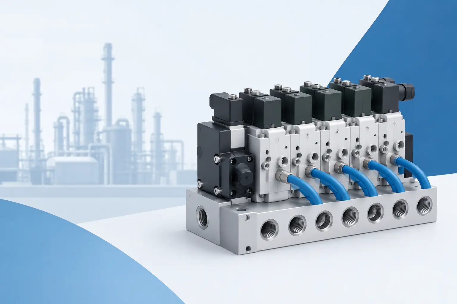
A valve manifold is rarely the largest line item in a machine build, but it can stop an entire station when the wrong configuration, connector, or replacement valve is specified. The best pneumatic valve manifolds are not simply the highest-flow assemblies. They are the manifolds that match the machine’s air demand, controls architecture, installation constraints, and maintenance plan without creating unnecessary spare-part complexity.
For plant engineers, panel builders, and MRO buyers, selection usually starts with a failed component or an existing part number. That is the right place to start. Before comparing alternatives, identify the installed valve series, valve function, coil voltage, fieldbus node if present, port thread, and manifold station count. A physically similar valve may not provide the same flow, electrical connection, or diagnostic behavior.
What Separates the Best Pneumatic Valve Manifolds
A pneumatic manifold combines multiple directional control valves into a common air distribution platform. Instead of piping each valve from individual supply and exhaust connections, the manifold routes supply air through shared channels and provides organized working ports for cylinders, grippers, vacuum devices, and other pneumatic actuators.
The practical benefits are clear: reduced tubing, fewer potential leak points, faster assembly, and cleaner machine layouts. The trade-off is that a manifold becomes a coordinated system. A change in valve family, communication node, or base plate can affect several functions at once. For that reason, the best choice is often the one that preserves compatibility with the installed machine rather than the one with the broadest published feature set.
High-quality manifold platforms from manufacturers such as Festo, SMC, Parker, Norgren, Emerson ASCO, and other established pneumatic suppliers are commonly chosen for repeatable performance and replacement availability. Within each product family, however, specifications vary substantially. Buyers should compare the exact valve and base configuration, not just the manufacturer name.
Flow capacity must match the real load
Flow is one of the first specifications to review. Undersized valves can slow cylinder extension, reduce clamping consistency, and make a machine appear to have a mechanical problem when the restriction is actually pneumatic. Oversizing every valve is not necessarily efficient either. It can add cost, consume more air, and provide little benefit for short-stroke or low-volume actuators.
Review the valve’s rated flow alongside cylinder bore, stroke, cycle time, supply pressure, tubing size, and any speed-control restrictions. A high-flow valve cannot compensate for undersized tubing, a clogged silencer, or a restrictive fitting. On fast cycling equipment, evaluate exhaust performance as closely as supply flow because trapped exhaust air is often the limiting factor.
Valve function determines machine behavior
A 5/2 valve is common for double-acting cylinders, while 3/2 valves are often used for single-acting actuators, air blow-off, and pilot signals. The choice between single-solenoid spring return and double-solenoid bistable operation also matters. A spring-return valve moves to its default state when power is removed. A bistable valve can remain in its last commanded position until it receives an opposing signal.
That behavior affects recovery after an E-stop, power interruption, or PLC restart. It should be determined by the machine’s safety and operating design, not selected casually as a replacement convenience. Confirm whether the original valve is normally closed, normally open, center closed, center exhaust, or another spool configuration before ordering.
Choose the Controls Connection Before the Manifold
A manifold’s electrical architecture can have more impact on installation labor than its pneumatic layout. Conventional hardwired manifolds work well for simple equipment and straightforward replacement needs. Each solenoid has its own connector or a multipin cable, making troubleshooting familiar and direct.
For larger machines, distributed I/O manifolds can reduce cabinet wiring and support more organized diagnostics. Common industrial networks include EtherNet/IP, PROFINET, EtherCAT, IO-Link, and Modbus TCP. The correct option depends on the PLC platform, machine network standard, available IP addresses, required update time, and maintenance capability at the site.
Do not assume that a manifold node using the same protocol will automatically integrate with the existing controls program. Verify the required device description files, output byte mapping, diagnostic data, connector type, and power requirements. A replacement node may also require configuration or addressing before the machine can return to service.
Voltage and connector details prevent avoidable delays
Most industrial pneumatic solenoids use 24 VDC, but the coil style and connection method still need confirmation. DIN connectors, M8 and M12 connections, multipin plugs, and integrated electronic modules are not interchangeable by default. In wet, dusty, or washdown areas, verify the environmental rating of the complete assembly, including cables, plugs, end plates, and unused port covers.
If a manifold is installed near heat sources or in a high-cycle application, review coil power consumption and temperature limits. Heat buildup may shorten coil life and can make diagnostics less reliable. In these applications, a manifold with individual LED indication and channel-level fault reporting can save significant troubleshooting time.
How to Compare Manifold Configurations
The manifold base is not just a mounting accessory. It defines port locations, shared supply and exhaust paths, pressure zones, station expansion options, and sometimes electrical connectivity. A correct valve mounted on the wrong base may leave ports misaligned or create an unintended pressure arrangement.
Pressure zoning is particularly useful when different actuators need different regulated pressures. A gripper may require lower pressure than a clamp, for example, while both remain on the same manifold assembly. Separate pressure zones can simplify plumbing, but they add specification detail. Confirm which stations belong to each zone and whether the base supports internal or external pilot air as required.
When comparing options, document these details before purchasing:
- Manufacturer and complete valve family or series designation
- Valve function, number of positions, actuation type, and default state
- Port size, thread standard, tubing and fitting requirements
- Rated flow, operating pressure range, and media compatibility
- Coil voltage, connector style, cable length, and ingress rating
- Manifold station count, blanking plates, pressure zones, and end plates
- Communication protocol, I/O addressing, diagnostics, and node part number
This information supports accurate sourcing and reduces the chance of receiving a component that is close but not usable. It is also valuable for creating a spare-parts record. A photo of the installed assembly helps, but a clear list of part numbers from valves, bases, cables, and network nodes is more dependable.
Replacement Versus Redesign
For an unplanned repair, replacing the existing valve or manifold component with the same manufacturer and part number is usually the lowest-risk path. It preserves port geometry, electrical wiring, PLC mapping, and machine documentation. Verify whether the manufacturer has issued a superseding part number and whether any accessory changes are required.
A redesign may be justified when a manifold family is obsolete, recurring failures point to an application mismatch, the machine needs added stations, or the controls system is being modernized. Treat this as an engineering change, not a like-for-like purchase. New manifolds may require different mounting dimensions, fittings, wiring, PLC programming, and pneumatic schematics.
Legacy equipment creates another decision point. A discontinued valve may still be available through industrial inventory channels, while a newer series may offer a longer support horizon. The right answer depends on production urgency, the number of identical machines, stockroom strategy, and how much validation time the plant can accept.
Procurement Checks That Keep Repairs Moving
Before placing an order, compare every available manufacturer code on the assembly. A manifold often carries separate identifiers for the valve, sub-base, end plate, cable, fieldbus module, and mounting hardware. Ordering only the visible solenoid valve may not resolve a damaged base, failed node, or incompatible connector.
For critical assets, consider keeping spare valves, blanking plates, fuses, connectors, and a preconfigured communication node where applicable. The appropriate stock level depends on lead time, machine criticality, and the number of installed units. A common manifold family used across several lines is usually a stronger spare candidate than a specialized one-off assembly.
When sourcing replacement automation components, provide the full part number, photos of labels, machine voltage, and application notes to the supplier. American Automation 24 can help buyers identify branded automation components and compare available options when the existing configuration is known. Clear identification shortens the path from quote to shipment and reduces return risk.
A properly specified manifold should make the machine easier to service, not merely functional on day one. Keep the final bill of materials, wiring reference, pneumatic schematic, and configured network details with the machine record. When the next valve fails at the end of a production shift, that documentation is often the fastest route back to operation.